Press Fit Tolerance Chart Mm

Sae J514 Hex Tolerance For Jic Fitting Size Chart Wrench Sizes Hex Wrench Hex

Sae J1926 3 Iso 11926 3 Metric Hex Size
Ball Bearing Fitting Series Basics Of Fit Charts Power Transmission Blog

Pin On Homeschooling

Appendix B Ansi Preferred Metric Limits And Fits Engineering Design Graphics Sketching Modeling And Visualization 2nd Edition Book
Preferred Mechanical Tolerances Metric Iso 286 Engineers Edge Www Engineersedge Com
25 h11 or 25 c11 a fit is defined by the basic size followed by the tolerance of each component.
Press fit tolerance chart mm. Geometric tolerances limits fits charts mechanical tolerances tables and calculators. The size ranges given are for typical size ranges utilized within industry. H9 d9 d9 h9 h9 c9 h9. Multiple fits of shafts of production and piston machines parts rotating very rarely or only swinging.
A feature tolerance is defined by the basic size followed by the tolerance designation. Type pm metric press fit headless bushings are the most popluar and least expensive. However with a bolt you can drill a hole with a diameter tolerance of 0 020 inches. 25 h11 c11 or separated with a dash ex.
Hole based fits should be preferred. Which takes us to our next area of discussion. The usage of these tolerances is advised for economic reasons. 25 h11 c11 fits are either based on the hole feature or the shaft feature.
With the press fit if your hole is 0 0007 inches too big you won t have any interference at all so tolerances become extremely important. Multiple fits of shafts of production and piston machines parts rotating very rarely or only swinging. Some of the selected preferred fits. This standard defines preferred limits and fits for press fits applications of non threaded cylindrical features.
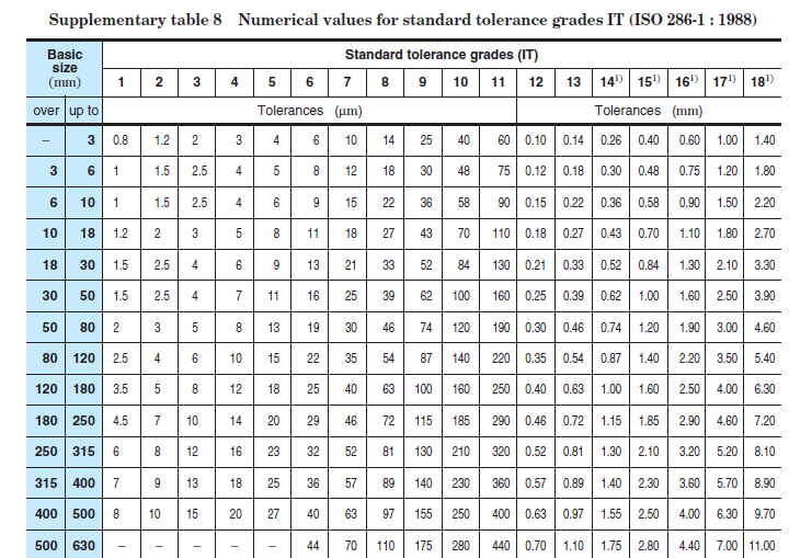
They re offered in a wide variety of configurations. The standard tolerance for the hole of grade 8 it8 25 i 25 0 001 56 0 039 mm the standard tolerance for the shaft of grade 7 it7 16 i 16 0 001 56 0 025 mm this is the complete explanation of all the 3 types of fits which are proved by the conditions and extreme cases. The tolerances defined in iso 286 1 are applicable to size range from 0 mm to 3150 mm but there are exceptional cases defined in the standard which depend on tolerance selection. If the calculation results given by the calculator are then this means the input parameters are not applicable according to iso standard.
This type of tolerance can be usable where any special requirements for accuracy in not essential but good for wide temperature variation heavy journal pressures and high running speeds. H9 e9 h8 e8 h7 e7 e9 h9 e8 h8 e8 h7 running fits with greater clearances without any special requirements for fit accuracy main fits of machine tools. Standard i d s o d s and lengths are millimeters mm. Preferred fits and tolerances charts iso ansi metric standards preferred fits and tolerance table for hole and shaft basis systems which are given in iso 286 1 2010 and ansi b4 2 1978 standards.
The following links are to general tolerance table charts for standard shaft hole fits per mcdonald douglas design guide machining tolerances. Some of the applications.

Shaft Tolerance An Overview Sciencedirect Topics
Https Staffweb Itsligo Ie Staff Sdalton Cad Notes Linear 20tolerances Pdf

Simple G Code Example Mill G Code Programming For Beginners

Pin By Ray Wang On Jic Jis Bsp Din Iso Sae Hydraulic Fittings Drawing Size Chart With Images

Is There Anything More Frustrating Than Seeing The Perfect Ring For A Friend But Not Having Her Ring Size Ring Sizes Chart Measure Ring Size Mens Rings Fashion
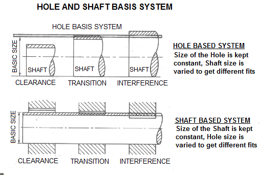
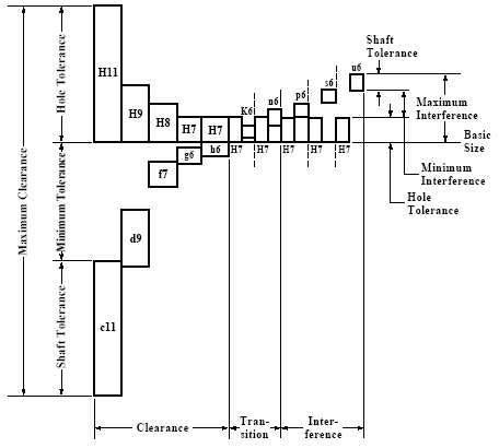
Hole And Shaft Basis Limits And Fits Hole Limits And Fits Hole And Shaft Tolerance

Fitting Tolerance Design Bearings Oiles
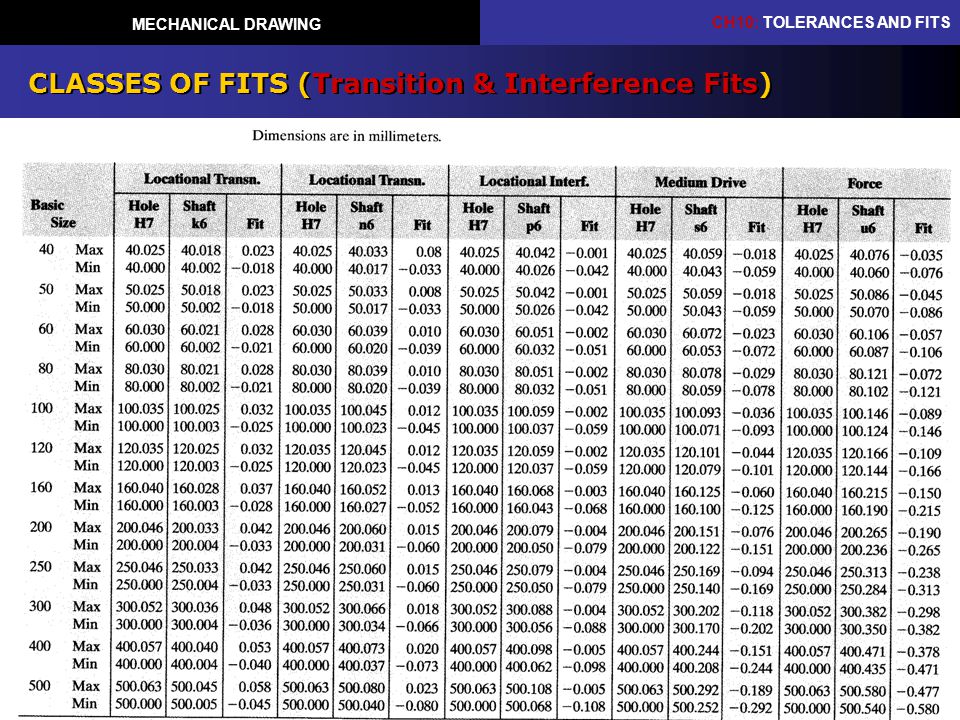
Mechanical Drawing Chapter 10 Tolerances And Fits Ppt Video Online Download

Pin By Ray Wang On Jic Jis Bsp Din Iso Sae Hydraulic Fittings Drawing Size Chart
4413chapter 10 Tolerancing

Cnc Fanuc G73 Pattern Repeating Cycle Cnc Program Example Cnc Programming Cnc Codes Cnc

10 Useful Mechanical Engineering And Manufacturing Wall Charts Omnia Mfg Mechanical Engineering Mechanical Engineering Design Engineering Symbols

Cnc Lathe Simple G Code Example G Code Programming For Beginners
Https Www Lima Lier Be Files Cms Datasheets Passingen Pdf

