Interference Fit Tolerance Chart
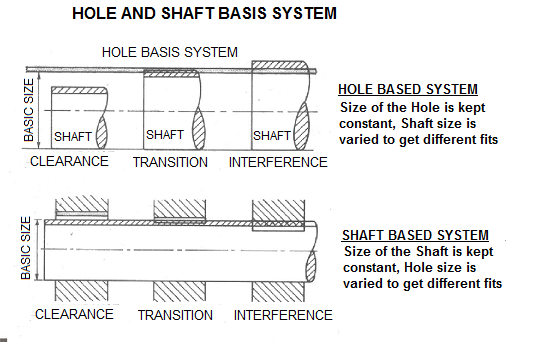
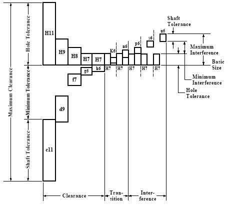
Hole And Shaft Basis Limits And Fits Hole Limits And Fits Hole And Shaft Tolerance
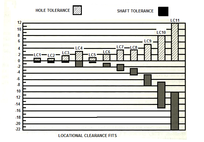
Locational Fits Locational Clearance Ansi Limits And Fits Locational Clearence Limits And Fits

Press Fit Calculator And Tolerances Free Software Cnccookbook Be A Better Cnc Er

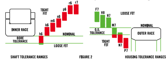
Ball Bearing Engineering Nmb Technologies
Http Home Iitk Ac In Anupams Me251 Tolerances Tables Pdf

Iso Tolerance Calculator Chart Clearance Hole Press Fit And More Cnccookbook Be A Better Cnc Er

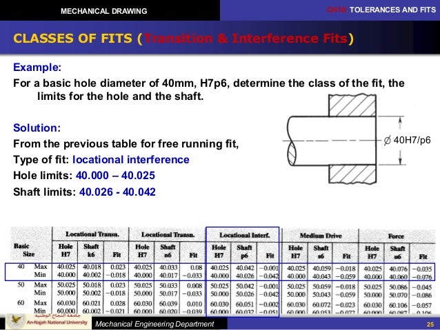
Class v locational interferance fit tolerance chart for holes and bolts per mcdonald douglas design guide machining tolerances.
Interference fit tolerance chart. Locational interference fits are used where accuracy of location is of prime importance and for parts requiring rigidity and alignment with no special requirements for bore pressure. The following links are to general tolerance table charts for standard shaft hole fits per mcdonald douglas design guide machining tolerances. Fits and tolerance calculator for shaft and hole according to iso 286 1 and ansi b4 2 metric standards. The schematic representation of the fit is also drawn.
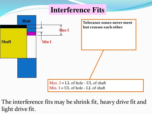
Multiple fits of shafts of production and piston machines parts rotating very rarely or only swinging. Conversely an interference fit is a fit where there will always be overlap in the joint between the specified mating shaft hole even at the minimum material condition values allowed by the shaft and maximum value allowed by the hole tolerance values i e the largest hole and the smallest shaft. Graphical representation of ansi b4 1 1967 locational interference fits table locational interference limits and fits for cylindirical parts ansi b4 1 1967 r1987 all limits shown in chart below are in thousandths of an inches. H9 e9 h8 e8 h7 e7 e9 h9 e8 h8 e8 h7 running fits with greater clearances without any special requirements for fit accuracy main fits of machine tools.
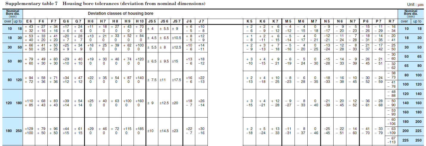
The tolerances defined in iso 286 1 are applicable to size range from 0 mm to 3150 mm but there are exceptional cases defined in the standard which depend on tolerance selection. Are shaft and hole designations used in american british canadian system abc. Mechanical tolerance standards charts geometric boundaries ii gd t reference book. The size ranges given are for typical size ranges utilized within industry.
Preferred Mechanical Tolerances Metric Iso 286 Engineers Edge Www Engineersedge Com
4413chapter 10 Tolerancing

How To Calculate The Right Tolerance For Making Parts Fit Quora
Ball Bearing Fitting Series Basics Of Fit Charts Power Transmission Blog

H9 Hole Tolerance A Pictures Of Hole 2018

Appendix B Ansi Preferred Metric Limits And Fits Engineering Design Graphics Sketching Modeling And Visualization 2nd Edition Book

Dimensional Tolerance And Fits
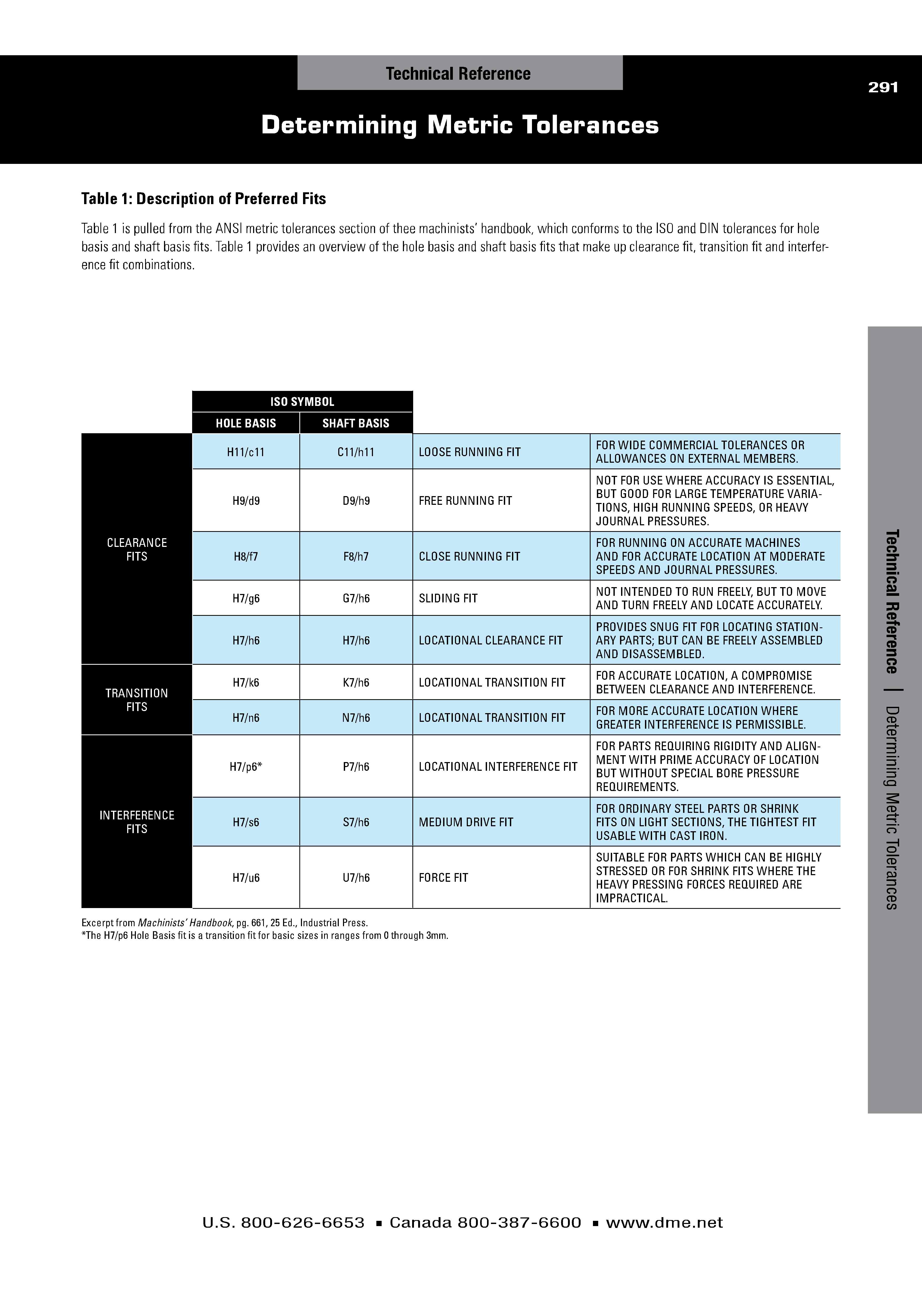
Determining Metric Tolerances

Press Fit Plastic How To Tips Projects

10 Fits Miniature Small Ball Bearings Engineering Information Eminebea
Ch 24 Limit Tolerance Amp Fits

2 Mounting Maintenance Repairs Services Nsk Global
Bearing Selection And Achieving The Right Press Fit
Tolerances And Fits Engineering Tolerance Steel